Formats for Labelled Transition Systems
These pages explain the storage formats for labelled transition systems (LTSs). For a general explanation of labelled transition systems see Labelled transition systems.
mCRL2 LTS format
An mCRL2 LTS file consists of a labelled transition system together with a declaration of the data types and action declarations. Each transition is labelled with a multi-action, which is a sequence of action labels each optionally having data arguments. States can also have labels. Such a label generally is a vector of data values corresponding to the values of process parameters in the linear process specification from which the lts was generated. But such a label can also be a set of such vectors. This typically occurs when a labelled transition system is reduced using (branching/weak) bisimulation in which case all labels of equivalent states are accumulated in a set and this set is used as the new label.
A labelled transition system contain probabilities. In this case a transition goes to
a discrete probability distribution. These can be viewed as
non-labelled states with outgoing transitions that are labelled with probabilities.
The sum of the probabilities of all outgoing transistion equals 1. Only a few tools
support probabilistic transition systems, such as ltsgraph and ltspbisim.
An LTS in LTS format requires relatively little diskspace as it is stored as a compressed, shared ATerm. This ATerm storage format supports streaming, and therefore labelled transition systems in LTS format can be streamed.
Files in the LTS format typically have the extension .lts.
As all data and action declarations are stored in the file format,
this format is very suitable to transform an LTS into a linear process
using the tool lts2lps.
A disadvantage of the .lts format is that it is not human readable.
For this, the LTS should be translated into .aut or .fsm format,
which can be done using the tool ltsconvert.
The aut format
The aut file format is a simple format for storing labelled transition systems. It is widely used by other tools, for instance the Caesar-Aldebaran or CADP toolset.
The syntax
The syntax of an Aldebaran file consists of a number of lines, where the first
line is a aut_header and the remaining lines are of type aut_edge.
An aut_header is defined as follows:
aut_header        ::=  'des (' first_state ',' nr_of_transitions ',' nr_of_states ')'
first_state       ::=  number
nr_of_transitions ::=  number
nr_of_states      ::=  number
Here:
first_stateis a number representing the first state;nr_of_transitionsis a number representing the number of transitions;nr_of_statesis a number representing the number of states.
An aut_edge is defined as follows:
aut_edge    ::=  '(' start_state ',' label ',' end_state ')'
start_state ::=  number
label       ::=  '"' string '"'
end_state   ::=  number
Here:
start_stateis a number representing the start state of the edge;labelis a string enclosed in double quotes representing the label of the edge;end_stateis a number representing the end state of the edge.
An example
The following example shows a simple labelled transition system of the dining philosophers problem for two philosophers, visualised using ltsgraph:
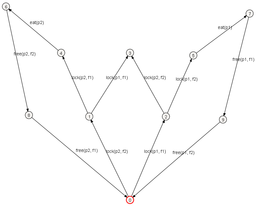
This transition system is represented by the following Aldebaran file:
des (0,12,10)
(0,"lock(p2, f2)",1)
(0,"lock(p1, f1)",2)
(1,"lock(p1, f1)",3)
(1,"lock(p2, f1)",4)
(2,"lock(p2, f2)",3)
(2,"lock(p1, f2)",5)
(4,"eat(p2)",6)
(5,"eat(p1)",7)
(6,"free(p2, f2)",8)
(7,"free(p1, f1)",9)
(8,"free(p2, f1)",0)
(9,"free(p1, f2)",0)
The probabilistic aut format
There is a straightforward probabilistic extension of the aut format.
The first state and each end state of an edge can be written as a discrete
probability distribution in the form \(s_0~p_0~s_1\cdots p_{n-1}~s_n\). This means
that state \(s_i\) is reached with probability \(p_i\) for \(i<n\)
and state \(p_n\) is reached with probability \(1-\sum_{i=0}^{n-1}p_i\).
Each probability is denoted as a fraction n/m where n and m are
positive numbers.
Note that this notation is a conservative extions of the probability free format.
If a state is reached with probability one, it suffices to only denote the
number of the state.
A probabilistic example
A small but typical example of a probabilistic aut file is given below.
The initial probability distribution chooses state 0 or state 1 with respective
probabilities 1/3 and 2/3. In state 0 an action is possible after which
either state 0 or 1 are chosen with equal probability. In state 1 only an action
b can be done, and after that state 1 is always reached:
des(0 1/3 1, 2, 2)
(0,"a",0 1/2 1)
(1,"b",1)
Acknowledgements
The Aldebaran format originally stems from the CADP toolset. To be fully compatible with the original syntax definition, the labels of the edges should consist of at most 5000 characters.
The FSM file format
An FSM file is a human-readable, plain-text file that specifies an LTS and
it supports not only labelling of transitions but also of states.
Besides that it can also express probabilities.
The states are numbered from 1 to n where n is the highest state number
occurring in the transition system, or n is the number of state labels.
In general these are the same, but there are situations where they
can differ, for instance when there are no state labels.
An FSM file typically has the extension .fsm.
The content of a FSM file has the following form:
FSM ::=PARAMETERS'\n' '---' '\n'STATES'\n' '---' '\n'TRANSITIONS'---' '\n' 'INITIAL_STATE'
containing four sections of which the last one is optional:
The first section specifies the state parameters and their domains;
The second section specifies the labels of the states of the LTS;
The third section specifies the transitions of the LTS;
The fourth section is optional and contains the initial state or initial probability distribution.
These sections are separated by lines that contain three dashes: ---.
The format of each of these sections is described separately below.
The parameters section
The parameters section defines the state parameters (or state variables) and their domains of possible values. In every state of the LTS, each of the parameters has one specific value from its domain.
Zero or more parameter should be specified. Every parameter is specified on a separate line of the following form:
PARAMETER ::=PARAMETER_NAME'('DOMAIN_CARDINALITY')'DOMAIN_NAME('"'DOMAIN_VALUE'"')*
containing the following items:
The parameter name: a string of alphanumerical characters;
The domain cardinality: a natural number;
The domain name: a string of alphanumerical characters;
A list of domain values: a space-separated list of quoted values, where every value is a string of characters that does not contain quotes (
").
The number of domain values should be equal to the domain cardinality. Note that when there are no parameters, this section is empty.
The states section
The states section defines labels for states. If the states have no label, this section can be left empty. The parameter list for every state is specified on a separate line of the following form:
STATE ::= (PARAMETER_VALUE)*
being a list of parameter values: a space-separated list of natural numbers.
The number of parameter values should be equal to the number of parameters defined in the parameters section, including parameters with a domain cardinality of 0.
The i-th value in the list specifies the value of the i-th parameter of the parameters section in the following way: a value of n specifies that in this state, that parameter has the nth value from its domain. These values are 0-based, meaning that a value of 0 corresponds to the first domain value of that parameter.
Every value should be at least 0 and smaller than the domain cardinality of the corresponding parameter. If that domain cardinality is 0, then the latter restriction does not apply and the value will be ignored.
The transitions section
The transitions section defines the transitions between the states of the LTS.
Every transition is specified on a separate line of the following form:
TRANSITION ::= SOURCE_STATE TARGET_STATE '"'LABEL'"'
containing the following items:
The source state: a positive natural number;
The target state: a positive natural number or a probability distribution;
The label: a quoted string of characters that does not contain quotes (
").
A value of n for either of the states indicates the n-th state of the states section. Each of these values should be at least 1 and at most the number of states specified in the states section.
A probability distribution is a sequence of pairs of state number followed by a fraction indicating the probability for this state to happen. This sequence is surrounded by square brackets. All probabilities in a distribution must add up to 1. A typical example is [ 1 1/2 3 1/4 7 1/4].
The initial state section
The initial state section is generally omitted and the initial state is by default assumed to be state 1. This section can be used to indicate an alternative initial state number, or it can be used to indicate that this transition system has a probability distribution over states as the initial state.
An example without probabilities
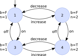
The following FSM file specifies the LTS depicted in the figure above. The state parameter values are indicated next to every state. The state identifiers used in the transitions section of the FSM file are shown inside every state:
b(2) Bool "F" "T"
n(2) Nat "1" "2"
---
0 0
0 1
1 0
1 1
---
1 2 "increase"
1 3 "on"
2 4 "on"
2 1 "decrease"
3 1 "off"
3 4 "increase"
4 2 "off"
4 3 "decrease"
An example with probabilities
A probabilistic example, based on a probabilistic fan controller, is given below:
s1_P(6) Pos  "2" "3" "4" "6" "1" "5"
b2_P(2) Bool  "true" "false"
b1_P(2) Bool  "true" "false"
k_P(3) Nat  "0" "1" "2"
---
0 0 0 0
1 0 0 0
1 0 1 0
0 0 0 1
2 0 0 0
2 1 0 0
3 0 0 1
0 0 0 2
4 0 0 0
3 0 0 2
5 0 0 0
---
1 [2 99/100 3 1/100] "on"
2 4 "fan_on(1, true)"
3 [5 99/100 6 1/100] "fan_on(1, false)"
4 7 "off"
5 8 "fan_on(2, true)"
6 9 "fan_on(2, false)"
7 1 "fan_off(1)"
8 10 "off"
9 11 "fail"
10 1 "fan_off(2)"
---
[1 1/2 2 1/4 3 1/4]